

ECU and CAN Bus Signal Integrity Analysis

Featured Brands


This application focuses on the Research & Development (R&D) and Quality Assurance stages of automotive electronics. Modern vehicles rely on Electronic Control Units (ECUs) communicating via CAN, LIN, or FlexRay networks. This system validates that the signals between sensors (ABS, Airbag, Engine Control) and the central computer are clean, noise-free, and within timing specifications.
How It Works
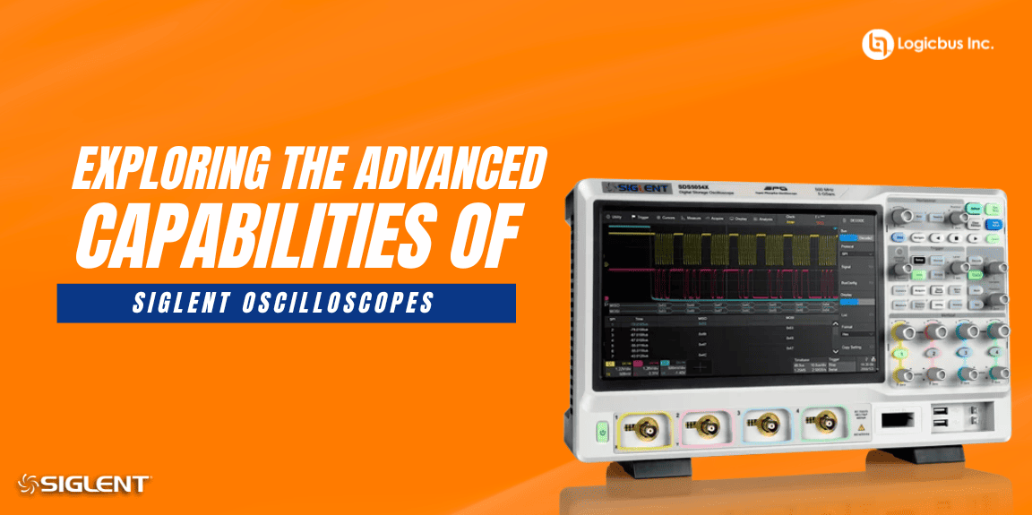
- Signal Acquisition: A high-bandwidth SDS2204X HD digital oscilloscope is connected to the vehicle's CAN bus ports or directly to the ECU pins. Using SDS2000HD-CANFD software, you can simultaneously capture and decode high-speed CAN data packets and analog waveforms to detect signal degradation or noise (“ghost” signals)
- Sensor Simulation:To check how the ECU reacts to anomalies, a programmable DC power supply SPD3303X and the arbitrary waveform generator option of the SDS2000HD-FG software are used to inject specific voltage drops or noisy sensor signals, simulating a faulty alternator or loose sensor connection.
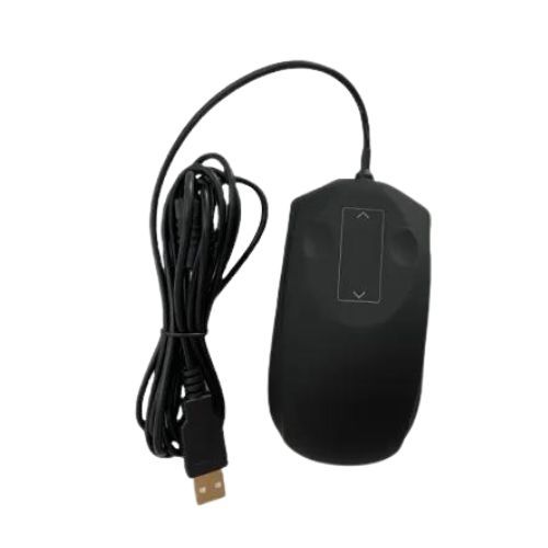
- Data Logging and Reporting: The oscilloscope SDS2204X HD is connected via LAN to an Industrial Panel PC TPC TPC-DCS. The engineer controls the test bench using a robust, oil-resistant industrial keyboard D-87W and mouse D-SME20-Black, ensuring the equipment survives the garage/lab environment.
Key Benefits
- Ensures safety-critical systems (brakes, steering) communicate without errors.
- Reduces troubleshooting time by decoding CAN Bus protocols directly on the scope screen.
- Robust user interface allows operation with greasy gloves in a workshop setting.
- Prevents costly recalls by detecting electronic glitches before mass production.


 ECU and CAN Bus Signal Integrity Analysis
 Exploring the Advanced Capabilities of SIGLENT Oscilloscopes
 Logicbus and Davo Electron: A Strategic Alliance Gaining Global Recognition in the Industrial Keyboard Market